On March 17th it was about push rods, control horns and linkages.
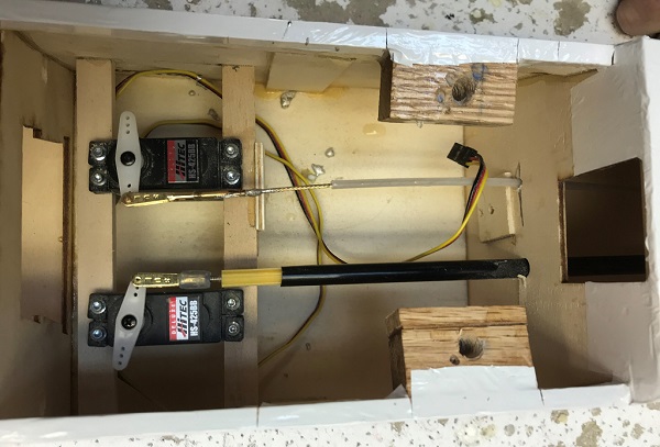
The first step was to get the push rods in place and attached to the servos (like you see in the featured image) all in there neutral position, the one isn’t… and may have lead to a correction being made later on if I’m not mistaken. In the image you can also see the hardwood glued into place to support the servos that have been screwed into it to keep them firmly in place during flight (so we hope). 🙂
When dealing with the push rod for the rudder, seen in the picture below, need to figure out where the control horn (the white piece attached to the rudder) needs to go to be in line with the rod coming out of the fuselage. Secondly you need to make sure it is in a place where it can be securely fastened, via screws, to the rudder. There is a back plate on the other side that the four screws pull in causing the front and back pieces making up the control horn to come together like a ‘clamp’ on the rudder.
Once the horn is in place, I then needed to figure out where to cut off the push rod, specifically the fixed outer casing (in black) and the inner yellow rod (actually moves) in order to have full motion of the control surface, which in this case means full left and full right on the rudder.
The control linkage (the metal part I screwed in earlier to the yellow push rod) then needs to be adjusted by screwing in/out so that it attaches to the control horn with the rudder in the neutral position. Don’t forget to ensure the servo arm (see top picture) is also in the neutral position as you want to have full range of motion for pushing and pulling the control surface.

Prior to attaching the elevator control surface the outer casing for the wire was attached to the ‘arch’ in the stab, but due to a design flaw (?) a wedge needed to be made and place under the casing since there was a requirement for it to be raised higher up off the stabilizer to connect properly to the elevator and be able to gain full motion.
Though a traditional push rod was not used, instead a piece of metal wire was fit through the tubing, a similar process was followed with figuring out where the control horn needed to be and making adjustments for proper attachment of the control linkage. This is seen in the pictures below and again ensuring the elevator and the servo are in the neutral position.


Lastly, due to an actual design flaw you will see two support wires that I attached from the bottom of the fuselage at the tail to the bottom outside edges (where there is balsa to screw into for support). Thanking to John V. for making the linkages for me… I believe it was out of fishing lure materials.
This is necessary as it was found that the tail of the aircraft, specifically the stabilizer would flex on the fin to much and not function as intended to provide stable flight.