On Nov. 11th made some more progress. Started with unboxing and getting 3 servos ready. For the two heavy duty control surfaces (elevator & rudder) using HiTech HS-645MG servos and for the throttle that doesn’t undergo the same amount of force a HiTech HS-425BB servo. For putting the control horns on figured out where each was going to be placed in the servo tray and insured the horns were pointing in a direction that wouldn’t interfere with each other. They go in from the bottom and (pilots perspective) right to left Elevator, Rudder and then Throttle as my engines throttle is on the left side. The middle servo control horn was cut to make room.
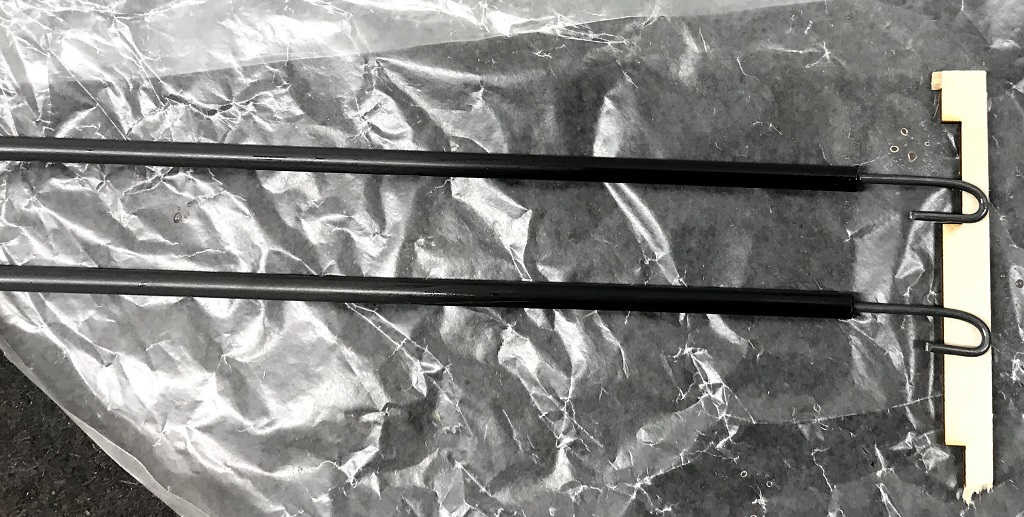
Next, I mixed up a batch of epoxy and glued the hooks Peter made into the carbon fiber push rods. Carbon fiber is used here instead of the plastic ones I’ve used in the past because this is a 3D aircraft, and like the servos, that will have to endure a lot more resistence and force while flying. Using a stick drooled epoxy into one end of the push rod until overflowing and then placed the metal hook in, repeated for the other. As seen in the featured image laid them out on the table and used a piece of wood to keep the hooks centered in the rods while the epoxy dried.
Next, I checked hinges to see how everything is lining up and that everything fit. It didn’t so needed to utilize the hinging tool to deepen the two outter hinges on each half of the stabilizer, making sure there was enough space for the elevators to freely move where the wire was to be.
The last task of the day was prepping the elevators and trailing edge of the stabilizer for the elevator wire. The steps to do this were as follows:
- Mark the center point of the wire
- Extend center marked on the tail behind the stab so I could see it
- With the center of the wire lined up:
- Verify previous markings (adjust as neccessary)
- Trace where wire goes over elevators while in place
- Since the vertical and horizontal stabilizer are glued into place, used tools to dig out a groove for the wire in the back of stab forcing through the glue, coming from both sides.
- Grooved out the elevator, where wire will recess into
- Found proper drill bit and drilled holes for wire in leading edge of elevator
You can see how things were left, with wire inserted, in the image below. The wire still needs to be glued into place.

Elevator Wire
Pingback: Building Aero3D Day 70 & 71: Push Rods and Rudder Hinges – Devin W.C. Ryan