This morning Peter came over and we tackled the remaining formers. We were very pleased with how the previous session set.
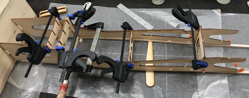
We started this session by completing Step 3 of the instructions; I use that term loosely with this build. The final result can be seen in the featured image above. I mixed up a batch of 30 minute epoxy and started with placing glue along the edges of former 5 (FU5). For all the pieces I avoided placing glue along the bottom notches as at this point we did not want to glue the doublers (FUA’s) to the balsa stringers. Once that was done we lightly clamped the piece in place.
Next, I placed glue along the edges of FU6, and during this process realized I never placed glue along the front and back of the tabs sliding into the doublers so backtracked and did that for FU5 and carried that process through to FU6 and onward as want to make sure there is glue on every surface that is in contact with part of another piece. We then lightly clamped FU6 into place. This procedure was then repeated for FU3/4 and FU2.
When doing the two at the front we ensured that the spacing between FU2 and 3 was correct by placing the landing gear mount in between (temporarily) while additional clamps were put in place. For the FU3/4 pairing we utilized two clamps, one for the top as it seemed to want to spread outwards and one for the bottom to ensure everything stayed in place.
It is worth noting that prior to tightening and as we tightend down the clamps we looked down the front of the fuselage to ensure all the formers were still lined up on the center line and doublers squared up against the block of wood.
We then moved to the tail where I glued former 10 (FU10) into place and left the square in place to ensure the piece remained vertical (that is squared up). The last piece glued was (from step 4) FU-ST-9, which is a piece of balsa 1⁄4” x 1⁄2” cut to 1 13⁄16” length from some scrap pieces Peter kindly brought over to start my scrap collection, perfectly suited for tasks like this! Same process here of marking the center on FUF and the balsa piece, even though we know there is going to be overlap, this ensures equal overlap on both sides, just encase.
From what we can tell of the diagrams FU-ST-9 will eventually be sanded down to be flush with the outer edges of FUF. For both Peter & I this is a new way of building (as there are no plans or additional instructions beyond these basic diagrams) so some discussion and me cracking out the manual online so I could zoom in on the PDF which allowed us to realize that coming up in Step 4 FUH is sitting flat, butting up against FU10 and on top of FU-ST-9, instead of the angle it appears to be in the printed version of the diagram (which didn’t make sense). FYI, in the kit FUH appers to actually be the piece labeled FUG.. though FUG is suppose to be hardward… this is 1⁄8” ply.
That concluded another session, as we could touch nothing else until the glue dries.
