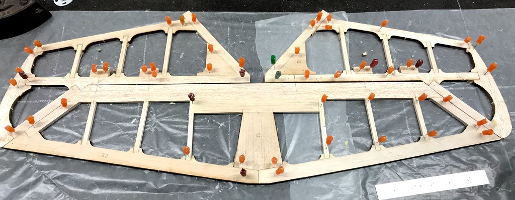
Wednesday Peter came over and we got to work on the aircraft. I replaced the defunct far right rib of the horizontal stabilizer (image above) with a new one. We then marked a center line on the trailing egdge and rib so that when we placed the rib back we knew its positioning.
We then got to work gluing all the ribs into place as well as the two end pieces. Once that was done, and ribs were pinned in place, placement for the hinges were marked across the elevator and trailing edge of the stabilizer. We also glued some 1/2” balsa blocks behind the elevators leading edge where the hinges are going to be for added support. You can see these, along with the glued ribs, in the featured image at the top. There will be 6 hinges total, 3 on each side.
Next we moved back to the rudder & fin.
Since the top of the rudder was previously glued we new that was our fixed point and had to figure out how the rest of the fin and elevator came together. Using my big ruler as a stright edge we shifted the elevator up keeping the leading edge in line with the leading edge of the fin and then pinned back in place.
From there moved existing pieces on the table to the appropriate locations along with figuring out the addtional pieces by scrutinizing the diagrams (instructions) to determine what was what.
You’ll notice, in the image below, the trailing edge of the fin buts up against the leading edge of the rudder. This will eventaully be sanded to a ‘V’ shape and hinges will be put in place as part of the attachment location for the control surface.
By eyeballing the diagram it was determined that 1/2” x 1/4” balsa stock was used as the main bottom support from the leading to trailing edge of the rudder (seen in the image below along the top of R3). This balsa piece appeared to be in line with the bottom of the fin and thus assisted in determining the location of R3. R3 appears to provide some additional strength for the rudder and will be where I hinge going into the back of the fuselage will go.
From there I measured and cut a piece of 3/8” x 1/4” balsa that makes up the bottom of the rudder, angled from R3 to the trailing edge.
I was then able to cut three 1/4” x 1/4” balsa ribs for the rudder that fan out from the leading to the trailing edge. The starting point, since there was a pre-made notch in the bottom of R2 was the top one, followed by the middle one, and then lastly the bottom. The top and bottom rib needed to be sanded to an angle at the end making contact with the trailing edge and for the bottom one at the other end as well making contact with the trailing edge.
Below you can see all the pieces pinned together. The next step, hopefully tomorrow, is to glue everything together.
