Tuesday was another 2hr building session, which is about my typical. When you look at what I got done to the uninitiated you may think to yourself “It took you that long to do what?”. In order to install the rudder and elevator push rods correctly it takes time.
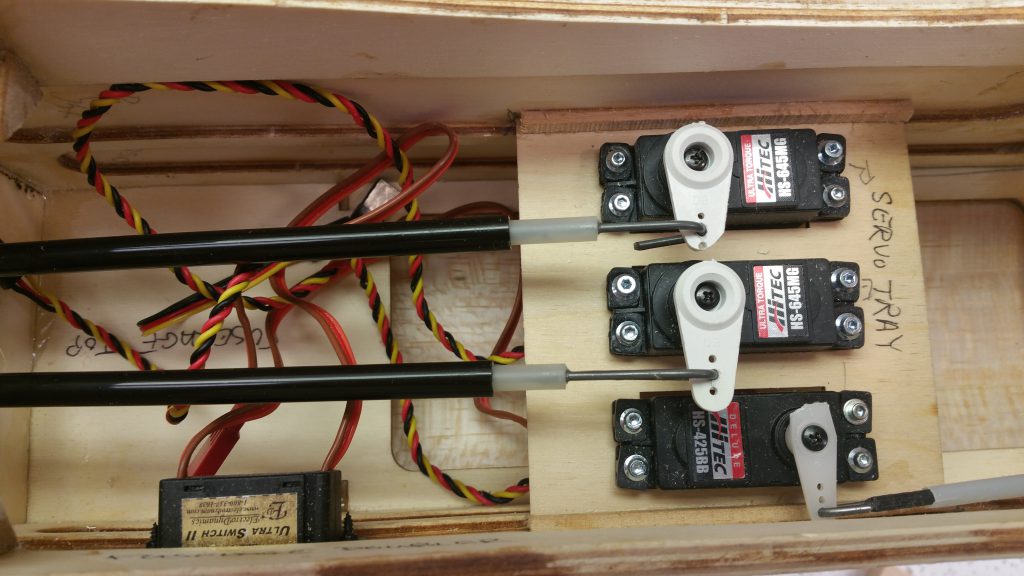
The first step is to figure out where the control horns need to be attached to the control surface (rudder & elevator). This is done by using a combination of the plans, to get a general idea where the horn needs to go as it’ll show where the support for it resides, and attaching the push rod to the servo to see where it lines up. The second allows you to determine the angle at which the control horn needs to be fastened to line up with the end of the push rod. As seen in the picture at the top I already have a hook in the push rod, which is attached to the servo arm.
Ensure that when you are installing the control horn and push rod the servo and control surface is in the neutral position.
Once this is determined you drill two holes through the control surface to act as the guides for the screws using a hand push drill, not electric, with a tiny bit. In my case it is two holes kitty corner to each other on the base of the control horn for fastening. When drilling you need to ensure you are going perpendicular to the surface and straight through, not at an angle, so take your time as it will pay off! I made this mistake and didn’t get it right so when placing the screws the opening on the back wasn’t lining up with the holes in the back plate causing issues. Thank-you John for the help correcting this and getting me on the straight and narrow for the elevator!
Now that the control horn is attached and lined up with the push rod you need to determine how much needs to be cut off both the inside piece and the outer casing to allow room for the clevis to be screwed into the inner piece and fasten to the control horn. You can see in the pictures that there is some excess of the inner tube showing on both ends. This is required to allow the servo arm to have full movement as the inner tube needs to be able to move far enough in both directions. Do not try to do this all in one cut, but instead:
- Put the push rod into the fuselage, attached to servo
- Line everything up
- Measure & mark about where some casing can be cut
- Measure & mark where some of the inner tube can be cut
- Remove the push rod and make the cuts
- Repeat until you have the desired fit
Remember that once the clevis is on you want it such that it is not screwed down to far either way to allow for adjustments if needed. Then pull the little rubber piece up to lock the clevis.

Once the push rods are installed you need to secure them to the fuselage. I did this using a hot glue gun. As you can see in the picture below I placed some hot glue on both sides of the holes where a push rod goes through the two formers.

