Yesterday we had a productive 2 hr building session. I love seeing my project slowly come together and take on more and more of a ‘total plane’ look/shape.
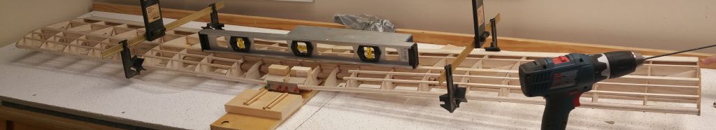
The evening started with checking out the ‘rig’ Peter created for drilling the holes for the dowels into the dowel support blocks. Because every planes wing is different you need to create this for each one! you can see the hole setup in the pic at the top of the post. The devices gripping the wings and actually slotted to hold the edges is set to ensure that the wing maintains the correct angle (if the angle is wrong the dowel holes will be off). These dowels are what will slip into the fuselage to hold the front of the wing while the back will be bolted on. Pinned to the front is the template for where the holes need to be made in order to match up properly with the fuselage. Then placing the drill bit into the device guiding it straight drilled into the support blocks providing a guide hole.

Here I went off plans and based on more experienced builders in the club. I’m going to place a hatch cover to provide easier access to the fuel tank. In order to do this need to reinforce T1 to provide support and a place for my hatch cover to screw into. I took a rectangular piece of scrap balsa wood and then figured out what width it needed to be, cut it and then traced the arch of the T1 piece followed by cutting it out and then sanding to get close to the same shape as T1. I didn’t want to sand perfect as will finish sanding once the glue dries so it is the same shape as T1.


I cut the hole for the switch for turning the plane on/off. For this I had to measure on the inside to see where I wanted the switch to be (between the edges of the doubler slot, to thick to go through the doubler as well) and then translate it to the outside where I did the work. I used the one piece as a stencil to mark the shape with a pencil. I did my best to make sure the hole was level so the switch won’t look all cockeyed once installed.
Then using a tiny drill bit I drilled a little hole in the four corners before going up to a bigger drill bit and drilling within the pencil lines to start opening up the hole. After that Peter used a tool to remove more followed by me finishing it off by sanding (not with sand paper! lol). You can see the switch placed in the slot in the pic below. Will need to remove for covering.

The last task of the evening was getting the stabilizer attached to the fuselage. First marked the center of the tail (where the stabilizer will sit) followed by centering the stabilizer on the back of the fuselage and penciled the lines to mark where glue needed to be applied. Then taped both the sides of the fuselage and next to the pencil marks on the stabilizer to ensure no excess glue gets stuck to those surfaces that will be covered.
Once that was done place glue on the stablizer and then set it on the fuselage, centered it both front and back using the pencil marks on the back and the center of the one ‘stick’ of wood for centering the front. We then clamped into place (used a block of wood so not right on the stabilizer) and once happy placed weight to hold in place.

This concluded another building session and next time I should be able to get a nice picture to really show the plane taking shape!