Today Peter & John came over. John and I focused on figuring out how to piece together the tail, specifically the stabilizer and elevators. The ‘plans’ for this build leave a lot to be desired and I’m hoping anyone else trying to build this aircraft is able to use these posts to subliment the diagram based instructions provided.
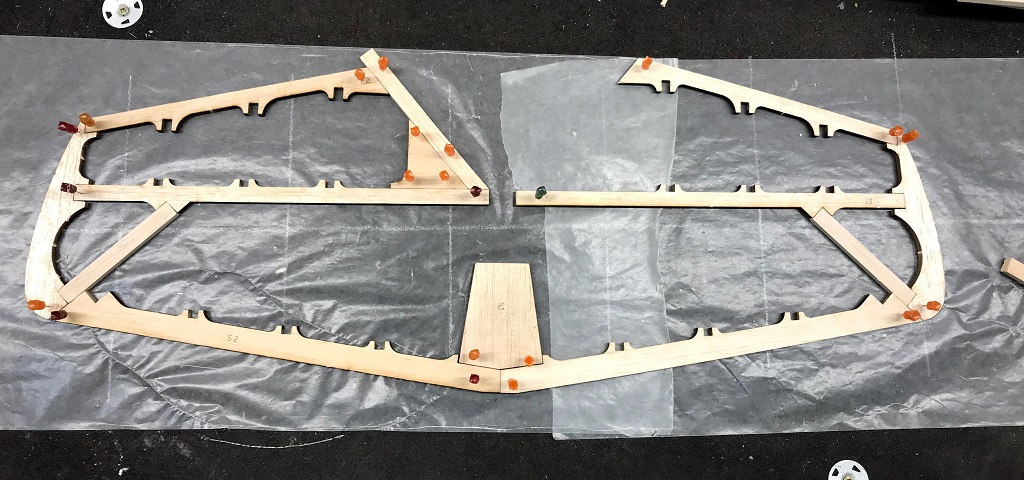
The tail frame is being built based on a picture of the completed balsa frame with no measurements for reference but by figuring out the pieces by look alone! This session was about figuring that out and gathering all the pieces to make up the perimeter of the stabilizer (front portion) and the two elevators (back portion that wraps around to the left and right sides) seen in the featured image above.
Since no measurements, angles, etc. were provided I’m going to explain how we went about getting the pieces we have together. So far we have just been pinning pieces into place and the plan is to build the entire stabilizer and elevaters, pinned into place, before even thinking about gluing anything together. Once we gathered all the pieces we sanded anywhere there will be a glue joint.
It was determined that the only way to build this with the information provided was to build from the outside inwards. Thus, the first pieces put together are S1 sitting inside the two S2 pieces making up the leading edge of the stabilizer (bottom edge in the featured image), to give us our starting point and angles.
Next we pinned the two E3 pieces, making of the left & right edges, and are actually part of the two elevators. Thus E3’s will not be glued to S2’s. We then slotted the two E1 pieces into the ‘middle’ slot within each E3 piece, ensuring they are level… not angled towards or away from S1, as these two pieces are going to make up the leading edges of the elevators.
With this done we were then able to determine the length of the 1⁄2” x 1⁄4” balsa to be 4 inches in length, but pieces were cut oversized and then sanded to fit both length wise and width wise for the bottom slot. At first the left hand one appeared to be longer so we cut it first and got it fitted in place. Then we did the same for the right side, which also worked out to be about 4 inches in length.
Once these were done we were able to move onto the trailing edge of the elvevators (E2), pinning both in a starting position. Then focusing on the (according to the featured image) left elevator was able to determine the angle of E2 and location of E4 (the triangle piece with 3 pins) based on the fitting of the 1⁄2” x 1⁄4” balsa piece, which we cut oversized to 6 inches, making up the inner side of the elevator. Once cut the one end was sanded to the appropriate angle such that it would sit flush with the ‘trailing’ edge of the inside end of E1. A combination of the angle of E4 and E2 needing to be flush with the balsa piece provided the final location of E4 and E2 with the outter edge corner being flush with the end of E2. The result of all this you can see pinned together in the image below. Once everything is glued into place, will sand down the balsa block to be the same angle and flush with the trailing ege of E2.
Worth noting is that the pieces didn’t fit together as snuggly as I would have hoped. Will have to see if the use of wood glue or medium CA will sufice when I get to the gluing phase. The key, from what we can determine, is to build from the outside (permiter) inwards. As this will dictate the length of the inside pieces (as well as angles) to match up with the necessary slots.
I am still confused about the two pieces that will make up the trailing edge of the stabilizer and how those need to be measured and cut… stay tunned!

Elevator Beginnings – Trailing Edge Perimeter